Inertia
Definition of inertia (Meriam Webster)
A property of matter by which it remains at rest or in uniform motion in the same straight line unless acted upon by some external force
The word inertia is frequently used in the context of an individual or business or government’s inability to make a relatively quick change due to factors that provide a large resistance to making such change. Thereby requiring external “forces” to overcome the inertia to facilitate change.
In the world of motion control we also speak about inertia – a resistance to change (in velocity). However, we also need to address this resistance to change in the context of the axis of rotation. A component of a given shape and mass in most cases will offer a different resistance to change (inertia) in one axis of rotation versus another axis of rotation unless it is symmetric about all of its axis – a sphere.
So we generally speak in terms of the “moment of inertia”.
Definition of moment of inertia (Meriam Webster)
A measure of the resistance of a body to angular acceleration about a given axis.
In the simplest of motion systems there is a motor, a load and a coupling of the motor to the load. One can also make the argument that there is also a coupling of the motor and the load to their respective mechanical terminations such as a machine frame. For this discussion we will assume that those terminations are rigid and offer no impact on the performance of the motion system.
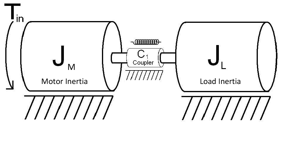 The drawing above depicts a motor, a coupling (shown as a torsional spring) and a load which in this case is a cylinder/disc with a given diameter and mass. The torsional spring is not a real world example of a coupling but will be used to help explain how excessive compliance in a coupling can impact performance of a system.
The Inertia of the cylinder/disc can be calculated by knowing its Mass (M) and radius (R).
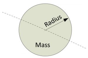
(for a disc rotating about the center of its axis as shown in diagram)
Some observations regarding the inertia formula:
- Mass (M) is directly proportional to inertia, if the mass doubles the inertia doubles
- Radius (R) impacts inertia by its square, if the radius of the disc doubles the inertia increases by a factor of four (22)
- The larger the Inertia (I) the more resistant the disc is to changing its rotational velocity, implying that more torque (rotational force) is required to increase its acceleration (change its velocity).
This brings us to torque.
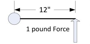
Torque is a measure of a rotating force through a radius. For example if you were to apply a 1 pound force to a lever that is 12” long at the end of the lever the applied torque would be 12 inch-pounds.
Torque = Force x Radius -> 1 pound x 12inch = 12 inch-pounds
The rotational output force of a motor is measured in terms of torque. When looking at motor spec sheets you will see various units of measure for motor torque such as foot-pounds; ounce-inches; newton-meters; etc. It is always a combination of a force and a length term, the order of the terms doesn’t matter (10 ounce-inches = 10 inch-ounces).
In order to change the rotational velocity of a load (acceleration), motor torque is required to overcome the inertia of the load:
Torque = Acceleration x Inertia(motor + load)
The larger the inertia (motor + load) and/or the amount of acceleration needed the more motor torque is required. This can have a significant impact on the motor size.
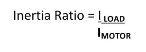
Inertia ratio impact on system performance
Inertia ratio is defined as the ratio of the load inertia IL to the motor inertia IM:
Generally speaking the higher the inertia ratio the greater the potential for poor system performance. A high inertia ratio combined with a coupling method between the motor and the load that is very compliant (springy) can produce very poor performance in terms of settling time and resonance.
A torsional spring was shown in the first diagram as a much exaggerated non-real world example of compliance. I represented the coupling this way so that you can get a better sense as to what can happen with a real coupling that has a certain compliance and is subjected to high accelerations with a large inertia mismatch.
The two most potentially damaging results due to this combination is excessively long settling times and uncontrolled system oscillation!
As you can imagine, if you had a very compliant (springy) coupling combined with a relatively large inertia mismatch (3:1 and higher as an example) you can see how a lagging – leading scenario can be set up between the motor and the load.
When the motor starts accelerating at a relatively high rate the load’s rotational position will lag the motor’s rotational position; as the motor starts decelerating at the end of a move the load’s rotational position due to its high inertia mismatch will not only make up the lag relative to the motor but will start leading it. Once the motor stops the load may continue to oscillate back and forth leading and lagging the motors stopped position until in dampens out.
In some cases a resonance can be set up that causes the load to continually oscillate even to the extent that it increases to a point where it can cause mechanical damage to components in the system. This could happen at any time in the rotation of the motor if it goes through a resonant frequency of the system.
This can be described mathematically by modeling the components of the system, creating a Laplace transform and analyzing the resulting bode plot for regions of instability. There are published articles on line that provide this analysis in detail. However, if you are not comfortable with high level mathematics as it applies to Laplace transforms and control theory you will have difficulty grasping a lot of it.
So what can be done to minimize the potential of these unacceptable performance issues?
- Select couplings that are less compliant, especially in the rotary axis plane.
- There are several manufacturers of motor couplings that provide high torsional stiffness, low backlash and hysteresis but provide lateral flexibility to accommodate shaft misalignment.
- For belt systems, consider using belts that are Kevlar reinforced which will minimize the “springiness” associated with the more traditional polyester belts
- The more rigid the coupling the higher the potential resonant frequency, it moves out to the right on a bode plot. This will allow the system to run at a lot higher speed while avoiding the chance of resonance.
- Reduce the inertia ratio between the motor and the load
- Gearing – adding a gear reducer between the motor and the load will reduce the reflected load inertia back to the motor by the square of the gear reduction. If a gear reducer of 5:1 is inserted between the motor and load the inertia mismatch is reduced by a factor of 25. This will also reduce the required motor torque by a factor of 5 (not counting the inefficiency of the gear box). This may also significantly reduce the size of the motor required due to lower motor torque requirements. Keep in mind that this is somewhat an iterative process in that by selecting a smaller motor due to less torque requirements the inertia of the motor will be reduced which will have to be looked at in terms of the overall system reflected load to motor inertia. Also, the motor RPM will have to be increased to overcome the speed reduction caused by the gear box.
- Select a motor with a higher inertia. There are families of motors, especially servo motors that offer motors with a higher inertia to help reduce the inertia ratio. There are also “pancake” style motors that have a high inertia
- Utilize advanced tuning parameters provided in high end servo amplifiers such as notch filters, feedforward, adaptive gain, and “fuzzy logic” etc. to help minimize the potential poor performance associated with high speed compliant systems.
For any questions or comments, please contact Tom Ruggierio truggierio@motionforautomation.com, phone# 844-MOT4AUT